SEMI-CNC Lathe Conversion - G4000 Build Log
Update 1: New (Old) Lathe
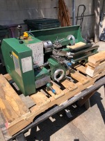
click thumbnails or use arrows to browse
Overview
I picked up this G4000 desktop lathe straight from eBay last year, and arranged some shipping, with some grunting, now it is on my workbench. The “desktop” part of the name is stretching the definition; it weighs around 250 to 290 lbs.
Desktop lathes like this rely entirely on gears to cut different thread pitches, meaning you are constantly swapping gears depending on what you are making. Inconvenient, but workable. The bigger problem is the half nuts.
The previous owner had already worn through one set. I replaced them, and they are already showing wear, grinding down and missing steps. The root cause of the accelerated wear is the leadscrew keyway: that slot runs the full length of the screw to drive the carriage auto-feed, but it traps debris and its sharp corners accelerate wear on anything riding against it.
Problems
- Change gear dependency for threading
- Rapid half nut wear from keyway debris accumulation
- Existing apron gears cannot hold position during facing cuts (too much backlash) unless the axis is locked down, so the old leadscrew cannot be used as driving mechanism
Current Solutions
- Electronic Leadscrew (ELS) - eliminates change gears entirely; thread pitch is now software-defined. https://github.com/kachurovskiy/nanoels
- Ballscrew conversion - addresses backlash issues with the apron feed. Due to the worn apron gears, the original setup cannot be used for CNC, it cannot hold position during facing or threading (I already tried it)
- Z-axis handwheel retained - manual feel preserved, but drive-by-wire has to be used.
Current Progress
In progress. Most of the major components are designed and in semi-working condition. Still refining parts and need to mill some parts out of aluminum or mild steel, outsourcing some sheet metal parts to SendCutSend.
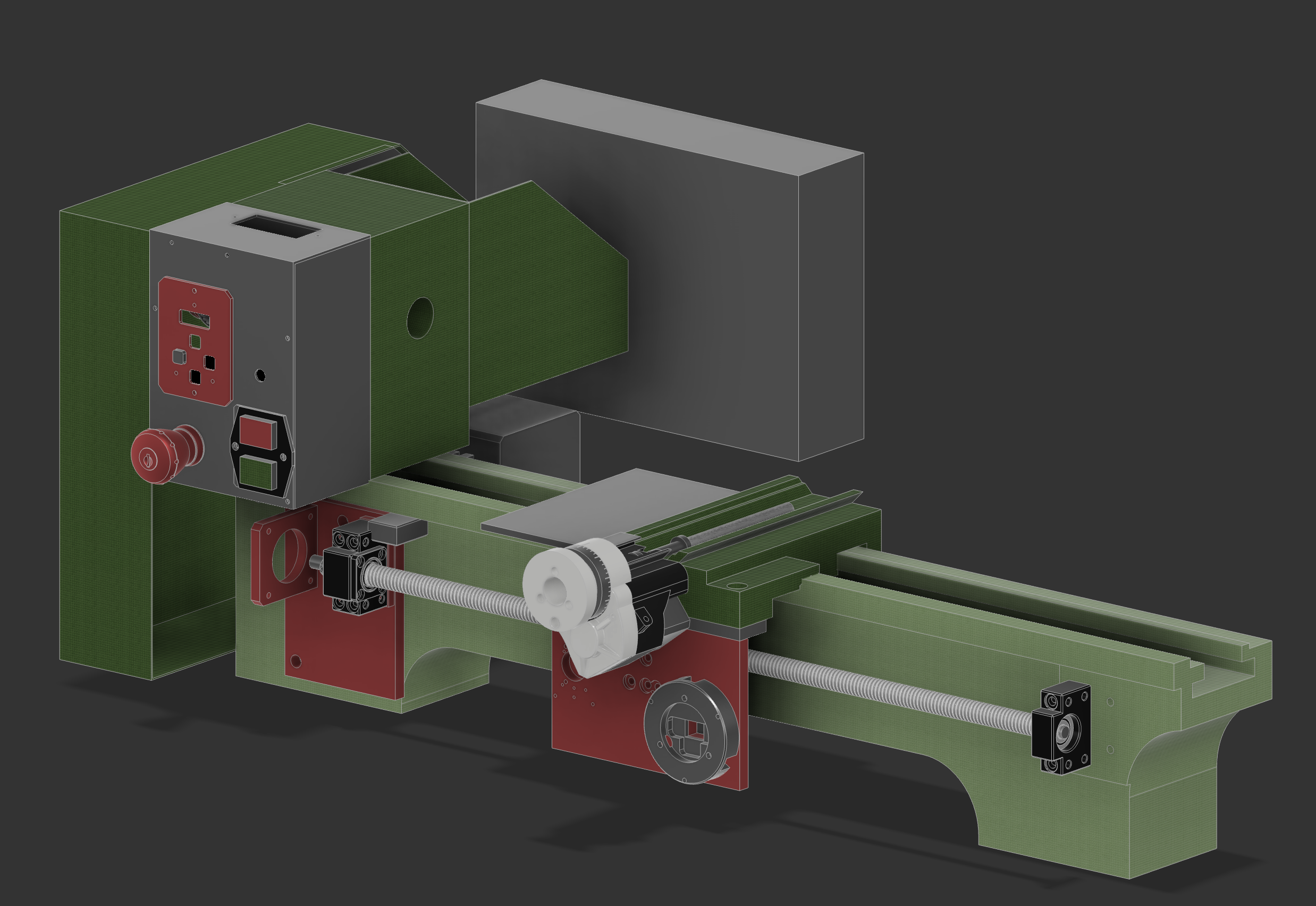
click thumbnails or use arrows to browse
Electronics
The ELS system is based on the open-source nanoELS H5 project. I ordered the board from PCBWay and components from AliExpress and Amazon. It is currently working nicely, most of the major components are set up, including motors for the Z and X axes and RPM sensors for the spindle.
I ran some test cuts and it is working nicely. In the next update I will have video of it running, along with a lot of refinements to show.
Update 2: Redoing the Motor Mount, Apron, and Lathe Calibration
A bunch of things went wrong recently, so this project slowed down for a bit. My mill kept eating bits due to awful spindle runout, thankfully, the company sent out a replacement. I had to re-tram the whole thing afterward, and it was a whole ordeal.

click thumbnails or use arrows to browse
Mill Tramming / Calibration
This machine saw some abuse from the previous owner, there was a big crash to the X-axis carriage, a huge gouge on the carriage's spindle facing surface, a broken lever, and a worn-out leadscrew.
A. Twist
I got some steel tube and used it to precisely level the lathe. Technically, you don't need to level a lathe, but it makes everything else so much easier. The problem: my floor was bad enough that the lathe's leveling feet alone weren't sufficient, since the floor itself was out of level. I had to add leveling feet to the table as well and that was an ordeal in itself, jacking the leg up to install the leveling feet from underneath. Still beats removing the lathe and mill and flipping the table to install it.
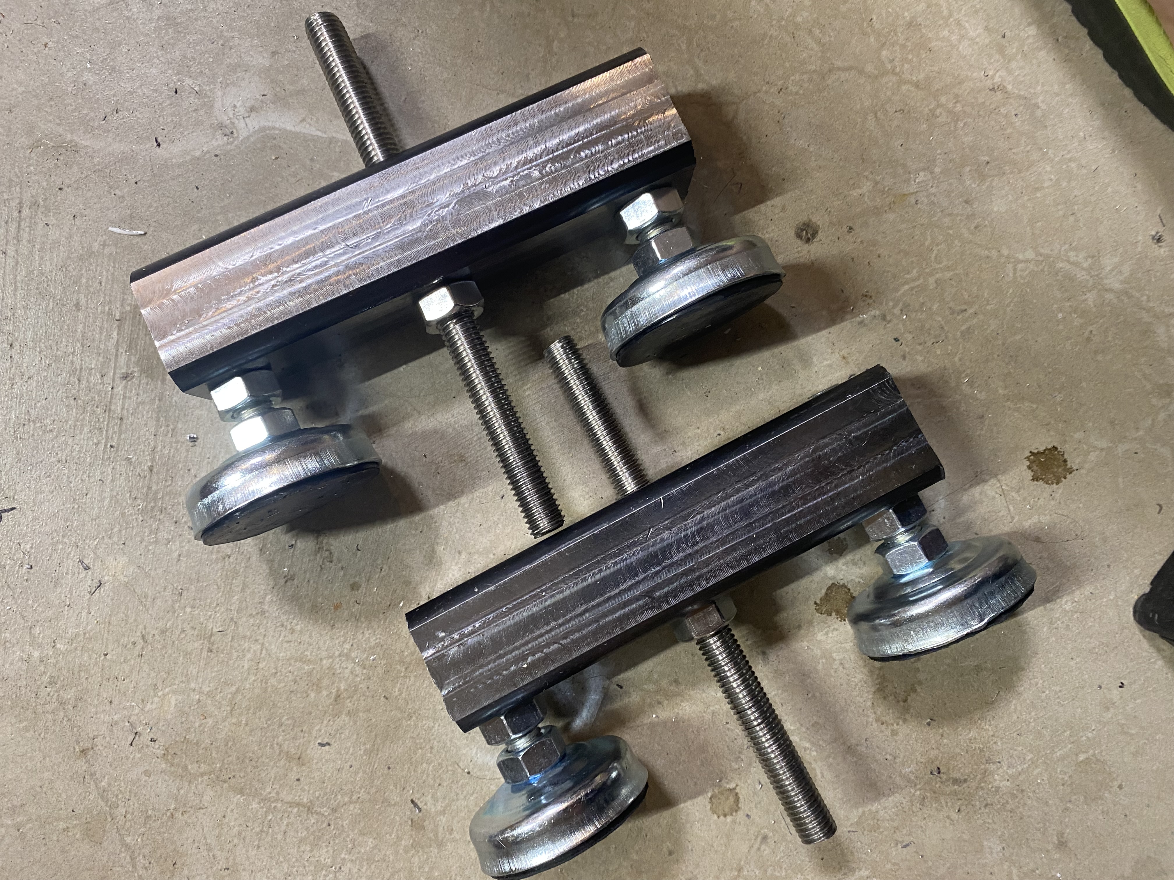
click thumbnails or use arrows to browse
B. Spindle Head Calibration
My lathe head had about a 7-thou taper across 6 inches. I didn't notice it when I first got the machine as I was too happy to have a new toy to play with.
My G4000 is the 1999 or earlier model, which only has 2 adjustment screws on the back of the head. So, I drilled 2 new ones, matching the newer version, to allow for better adjustment.
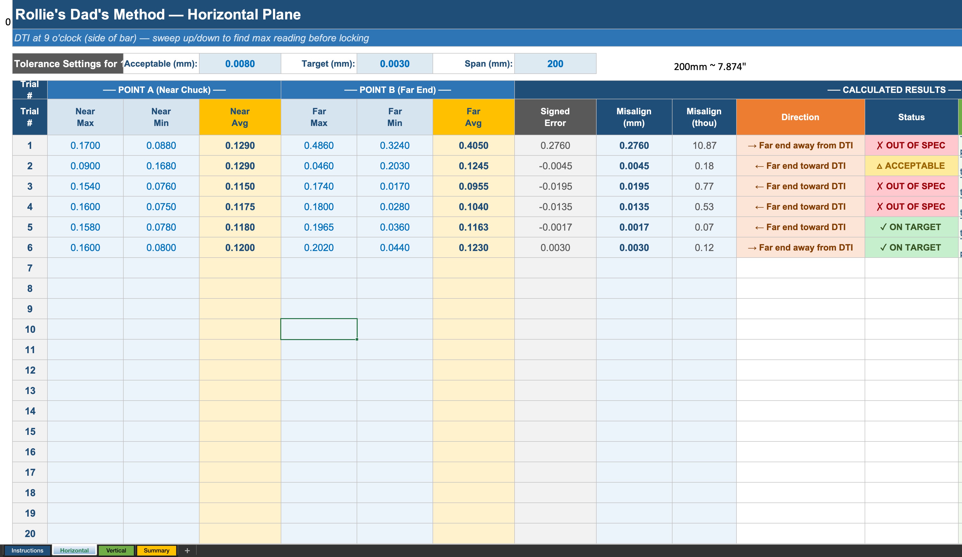
click thumbnails or use arrows to browse
Z-Axis Motor Mount and Apron
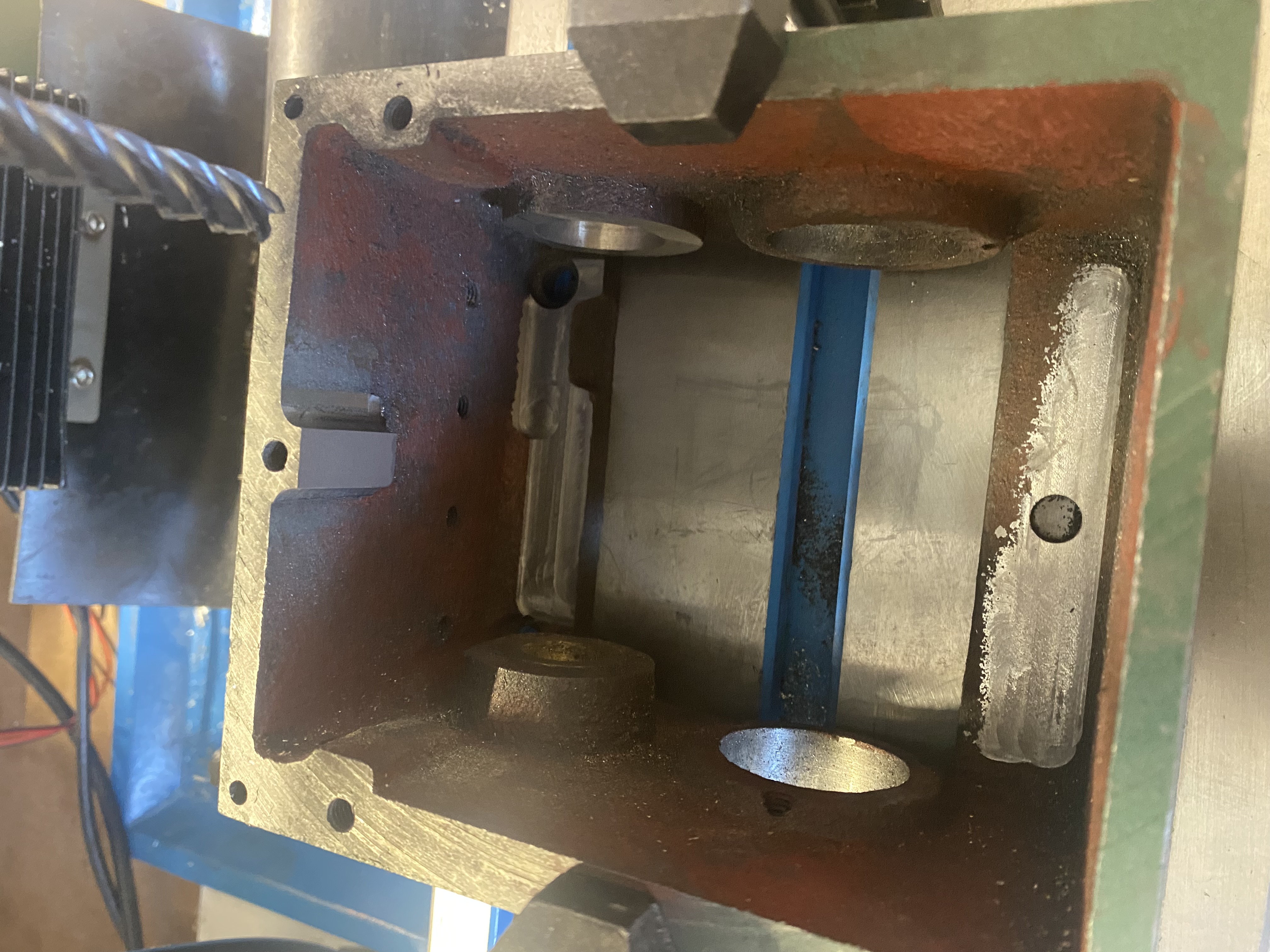
If you looked at the old pictures, these parts were CNC'd from aluminum, but since the old parts were going to be throw/stored away anyway, I might as well reuse them. It's heavier, and better damping.
click thumbnails or use arrows to browse