My Issues with Linear Shaft Gantries on Hobby CNCs
Sep 30, 2026
Introduction
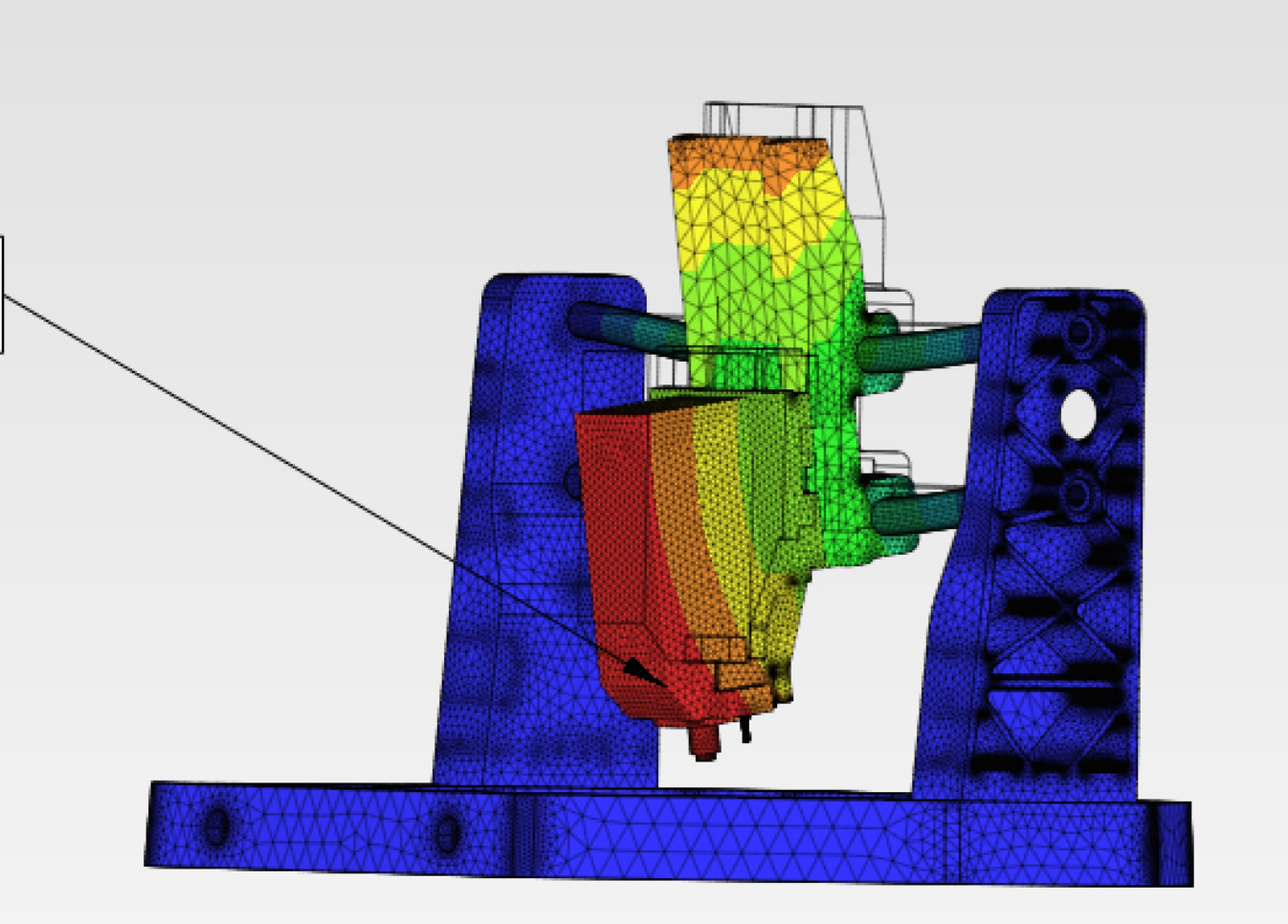
Many hobby CNCs carry the spindle head on a pair of round, unsupported linear shafts spanning the gantry. The Carvera Air, which I have, and the classic 3018 family and Nomad all use linear shafts.
The weakness of this design is flex. A round shaft supported only at its ends acts like a simply supported beam: it sags under the weight of the head even without cutting load, and the sag is largest in the middle of the span. All CNCs are going to have some kind of gantry sag, but the problem with these is that the sag is measured in thousandths of an inch.
The Carvera Air shafts are stainless steel, but only 22 mm in diameter. Engineering courses love beam deflection equations. If you have ever taken one, the equation below is probably familiar. It is just the maximum deflection of a simply supported beam with a single point load at the center. It's the classic textbook case. You can check this link for other cases.
δmax = PL3 / 48EI
Geometry enters through the second moment of area, I. For a rectangular beam, I = bh3/12, so doubling the height makes it 23 = 8 times stiffer. From this you can see by intuition how important geometry is, and why linear shafts are the weak link. And let's not even talk about torsion, which is also an important factor.
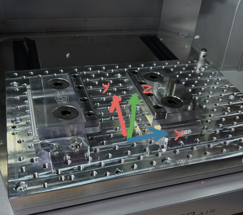
I ran into this when I tried to tram my machine. The Z height differed by about 0.001 in (0.025 mm) between the middle of the gantry and the outer edges. There was no reliable way to tram it, because the flex is much worse at the center than near the ends.
The problem with tramming
As I understand it, tramming a machine generally follows this order:
- Level and stabilize the machine. This mostly matters on heavier machines, where the frame can twist or distort.
- Align the X and Y rails for straightness and parallelism. On a hobby machine, jogging each axis from one end of travel to the other is usually enough for it to self align.
- Square (rack) the gantry. This is mostly for moving gantry machines, which typically drive each side of the Y axis with its own motor.
- Check X ⊥ Y, the actual squareness between the axes.
- Align Z to X and Y (Z ⊥ X and Z ⊥ Y).
- Tram the spindle.
There are more detailed versions depending on how far you want to take it, but these are the basics.
The trouble starts at step 4. Due to the flex, you can only use the Y edge to establish a datum, but when you try to sweep through the X axis, it is nearly impossible to dial it in truly. The shafts are not stiff enough or big enough that the spindle tilts with them. Even the alignment of the Y ballscrew and its brackets changes the tilt. That makes a true X ⊥ Y check nearly impossible. If anyone has ever trammed a mill before, you would know how maddening it is. Now multiply it by 10.
Steps 5 and 6 have the same problem. A side to side on x axis sweep shows the curvature: the error is worst at the center of the span and smallest near the supports. The best you can do is tram near the supports.
click thumbnails or use arrows to browse
PrePoMax FEA setup
This is not a FEA tutorial. I only took one FEA course in university, where we used Abaqus and mostly analyzed trusses and beams. I know the basics and I'm rusty. In industry, companies usually have a dedicated FEA analyst, since it can get complicated and also reliability.
I used PrePoMax, which is free. Its interface is similar to Abaqus, though it isn't as powerful as commercial software.
Settings
| What I used | Setting |
|---|---|
| Constraints | Parts joined with Tie constraints |
| Load | Gravity |
| Boundary condition | Entire bottom face of the base fixed |
Fixing the whole bottom face isn't ideal; fixing only the four feet would be more realistic. It's still a good enough model for what I'm looking at, which is the relative flex of the gantry shafts.
Quick convergence check
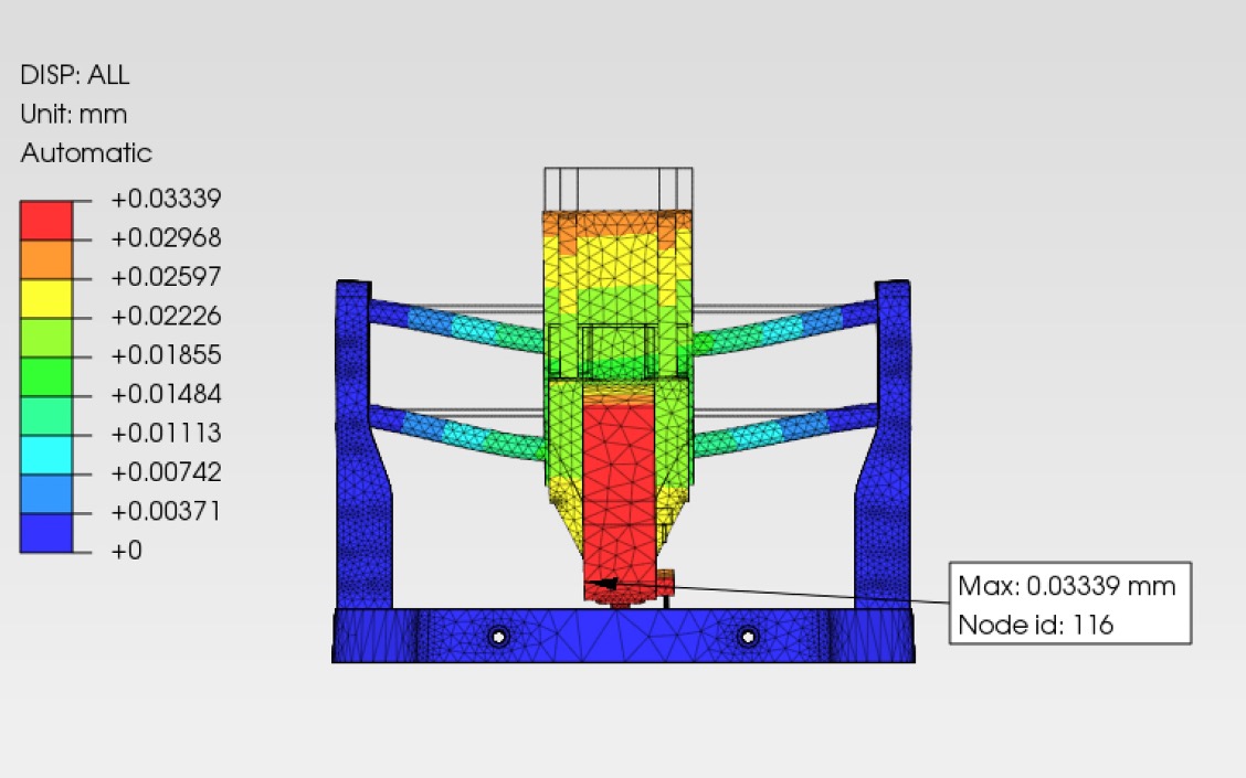
The max displacement converged at about 0.0204 mm, with the peak at the tool tip, which is pretty much what I got when I measured it. Sweeping the bed from left to right (X axis) showed about 1 thou, or ~0.0254 mm. I only checked convergence on displacement, since I only want to look at displacement. It's much cheaper in time and computing power than stress, and with an assembly it's easier to get stress wrong (different part mesh parameters, contact between parts), and there's no realistic way for me to measure stress.
| Run | Mesh | Max displacement (mm) | Change from previous |
|---|---|---|---|
| 1 | Coarse | 0.03339 | - |
| 2 | Medium | 0.02036 | -39% |
| 3 | Fine | 0.02035 | -0.05% |
Refining from run 2 to run 3 changed the result by less than 0.1%, so the medium mesh is already converged for displacement.
click thumbnails or use arrows to browse